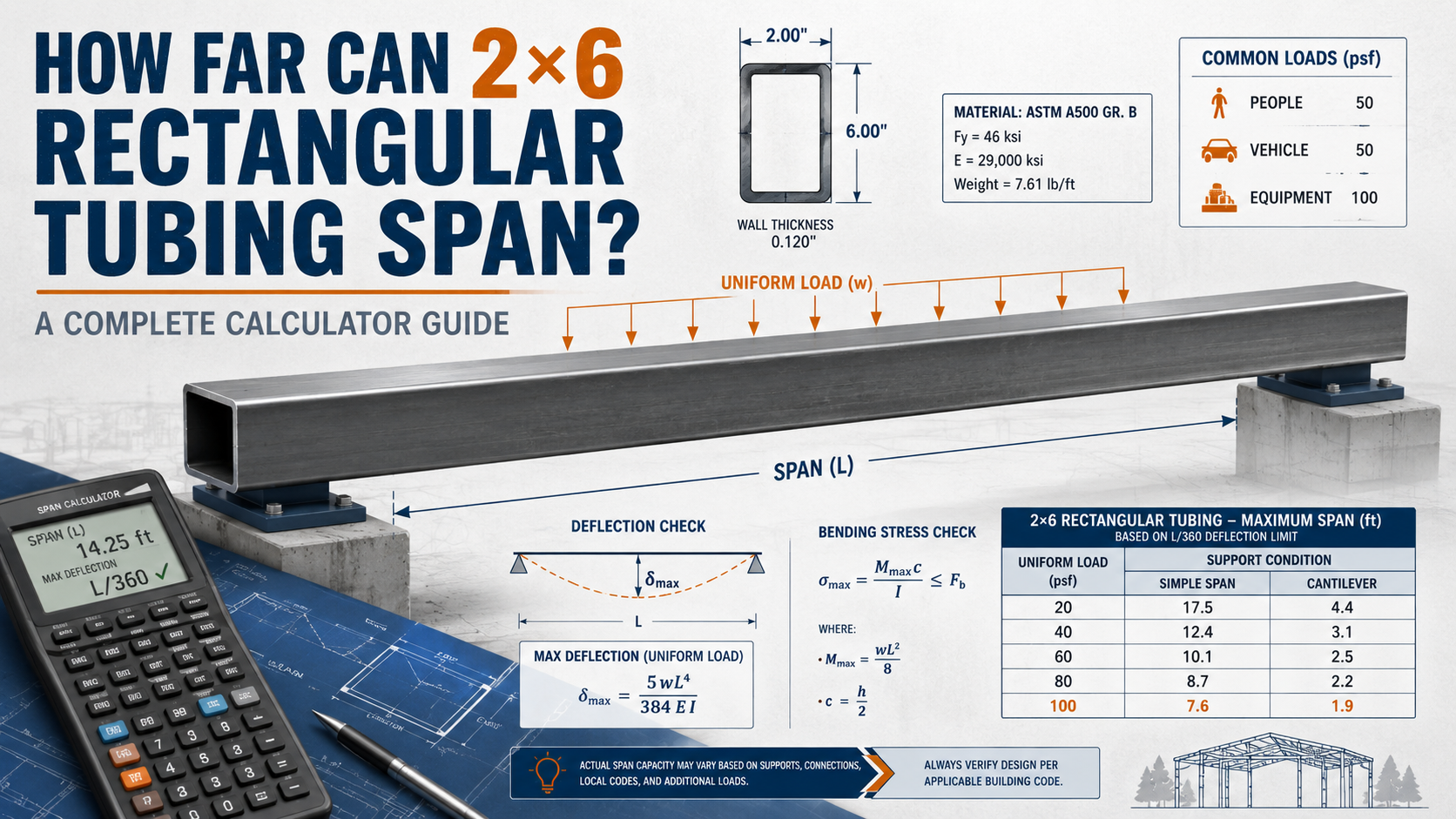
How Far Can 2×6 Rectangular Tubing Span? A Complete Calculator Guide
When planning a construction project involving steel framing, one of the most common questions is: how far can 2×6 rectangular tubing span?
Whether you are building a trailer frame, a mezzanine floor, a gate, roof supports, or structural framing, understanding the span capability of 2×6 rectangular hollow section tubing is critical for safety, performance, and code compliance.
This guide explains the main factors that affect span distance, the engineering formulas used by span calculators, practical load tables, and a real-world example that shows how a basic span check works.
What Is 2×6 Rectangular Tubing?
2×6 rectangular tubing, also called HSS 2×6 or RHS 2×6, refers to hollow structural steel tubing with nominal dimensions of 2 inches by 6 inches.
These tubes are commonly manufactured through electric resistance welding or submerged arc welding processes. In construction and fabrication, they are often supplied as ASTM A500 Grade B or Grade C steel, with typical yield strengths of 46 ksi or 50 ksi.
Common Wall Thicknesses for 2×6 HSS
| Wall Thickness | Approximate Weight | Typical Use |
|---|---|---|
| 3/16 inch, 0.188 inch | 8.15 lbs/ft | Light framing, gates |
| 1/4 inch, 0.250 inch | 10.51 lbs/ft | General structural use |
| 5/16 inch, 0.313 inch | 12.70 lbs/ft | Medium-load framing |
| 3/8 inch, 0.375 inch | 14.72 lbs/ft | Heavy-load applications |
The span capacity depends heavily on wall thickness, steel grade, orientation, load type, support condition, and whether the member is laterally braced.
Key Factors That Affect Span Distance
Before using any span calculator, it is important to understand the variables that determine how far 2×6 tubing can safely span.
Orientation
The orientation of the tube has a major effect on strength and deflection.
Strong axis orientation means the 6-inch dimension is vertical. This gives the tube much greater bending resistance and allows the longest practical span.
Weak axis orientation means the 2-inch dimension is vertical. This greatly reduces bending resistance and shortens the safe span distance.
For most beam applications, 2×6 rectangular tubing should be installed with the 6-inch dimension vertical unless the design requires otherwise.
Load Type
Different load types create different bending and deflection behavior.
A uniformly distributed load is spread evenly along the beam. Examples include flooring, decking, roofing, or a trailer deck.
A concentrated load, also called a point load, is applied at one location. Examples include a person standing at midspan, a machine base, or an equipment anchor.
Combined loads occur when dead load, live load, equipment load, snow load, or other forces act together.
Support Conditions
Support conditions also influence span capacity.
A simply supported beam rests on supports at both ends. This is the most common condition used in basic span tables.
A fixed-end beam has rigid connections at the ends. This can reduce deflection but increases stress at the connections.
A cantilever beam is fixed at one end and free at the other. Cantilever spans are much more limited and require careful engineering.
Lateral Bracing
Steel beams can lose capacity if they are not properly braced against lateral-torsional buckling.
For rectangular tubing, full lateral support helps the member develop its intended bending capacity. Unbraced members may need shorter spans or larger sections.
Allowable Deflection
A beam may be strong enough to carry a load but still deflect too much for practical use.
Common deflection limits include L/240 for general use and L/360 for applications with sensitive finishes or stricter performance requirements.
For example, a 10-foot span at L/240 allows a maximum deflection of 0.5 inches.
The Engineering Behind Span Calculators
Professional span calculators use basic beam mechanics to estimate bending stress and deflection.
Bending Stress Formula
σ = M / S
Where:
σ = bending stress, psi
M = maximum bending moment, in-lb
S = section modulus, in³
Maximum Moment for Common Load Cases
| Load Case | Maximum Moment Formula |
|---|---|
| Simply supported beam with center point load | Mmax = PL / 4 |
| Simply supported beam with uniform load | Mmax = wL² / 8 |
| Cantilever beam with end point load | Mmax = PL |
Deflection Formulas
| Load Case | Deflection Formula |
|---|---|
| Simply supported beam with center point load | δ = PL³ / 48EI |
| Simply supported beam with uniform load | δ = 5wL⁴ / 384EI |
Where:
E = modulus of elasticity for steel, approximately 29,000 ksi
I = moment of inertia, in⁴
L = span length, inches
w = uniform load, lb/in
P = point load, lb
Section Properties for 2×6 HSS Tubing
To use a span calculator correctly, you need accurate section properties. The following are approximate values for common 2×6 HSS tubing.
2×6 HSS with 1/4 Inch Wall, Strong Axis, 6 Inch Vertical
| Property | Approximate Value |
|---|---|
| Area | 3.37 in² |
| Weight | 10.51 lbs/ft |
| Moment of inertia, Ix | 15.3 in⁴ |
| Section modulus, Sx | 5.1 in³ |
| Radius of gyration, rx | 2.13 in |
2×6 HSS with 1/4 Inch Wall, Weak Axis, 2 Inch Vertical
| Property | Approximate Value |
|---|---|
| Moment of inertia, Iy | 2.3 in⁴ |
| Section modulus, Sy | 2.3 in³ |
| Radius of gyration, ry | 0.83 in |
These values are approximate. For final design, always use manufacturer tables, the AISC Steel Construction Manual, or calculations prepared by a licensed structural engineer.
Practical Span Guidelines for 2×6 Rectangular Tubing
The following span values are approximate planning guidelines for simply supported 2×6 HSS, using steel with Fy around 50 ksi, strong-axis orientation, and proper lateral support.
These examples assume typical construction loading, including a live load of about 40 psf and a dead load of about 10 psf.
These values are not a substitute for engineering design. They are intended for early planning only.
Span Table for 2×6 HSS, Strong Axis, Simply Supported
| Wall Thickness | Maximum Span for UDL Around 50 psf | Maximum Span for Light Load Around 25 psf | Approximate Midspan Point Load |
|---|---|---|---|
| 3/16 inch | 6–7 feet | 8–9 feet | 800 lbs |
| 1/4 inch | 8–9 feet | 10–11 feet | 1,200 lbs |
| 5/16 inch | 9–10 feet | 11–12 feet | 1,600 lbs |
| 3/8 inch | 10–11 feet | 12–13 feet | 2,000 lbs |
Span Table for 2×6 HSS, Weak Axis, Simply Supported
| Wall Thickness | Maximum Span for UDL | Approximate Midspan Point Load |
|---|---|---|
| 1/4 inch | 3–4 feet | 300 lbs |
| 3/8 inch | 4–5 feet | 500 lbs |
The key takeaway is simple: orienting 2×6 rectangular tubing with the 6-inch dimension vertical can more than double the practical span capacity compared with weak-axis orientation.
Step-by-Step: How to Calculate Span Yourself
If you want to build your own span calculator or verify a specific application, follow these basic steps.
Step 1: Determine Your Loads
Start by calculating the total load in pounds per linear foot or total pounds.
Dead load includes the weight of the tubing itself and any permanent attachments.
Live load includes temporary or variable loads such as people, furniture, equipment, snow, or stored materials.
A common load combination may use dead load plus live load for allowable stress design, or 1.2 times dead load plus 1.6 times live load for LRFD design.
Step 2: Choose Allowable Stress
For ASTM A500 Grade C steel with Fy = 50 ksi, a common allowable bending stress for ASD may be about:
0.60 × Fy = 30 ksi
For LRFD design, bending strength is commonly checked using:
ϕMn
where ϕ is often taken as 0.90 for bending.
Step 3: Calculate Required Section Modulus
Srequired = Mmax / Fallowable
This tells you how much section modulus the beam needs to resist the calculated moment.
Step 4: Check Deflection
After checking bending strength, check deflection.
δcalculated < δallowable
Common limits include L/240 and L/360, depending on the use of the structure.
Step 5: Check Shear
For short spans with heavy loads, shear may control the design.
A simplified shear check may use:
Vallowable = 0.40 × Fy × Aweb
For critical structures, shear should be checked using applicable steel design standards.
Real-World Example: Trailer Frame Application
Scenario
You need to build a trailer frame using 2×6×1/4 inch HSS with 50 ksi steel. The tube spans 8 feet between cross members. The deck carries a uniformly distributed load of 1,500 lbs total.
Given
Span, L = 8 ft = 96 in
Total uniformly distributed load, W = 1,500 lbs
Uniform load, w = 1,500 / 96 = 15.63 lb/in
Sx for 2×6×1/4 inch HSS ≈ 5.1 in³
Ix ≈ 15.3 in⁴
E = 29,000,000 psi
Bending Check
Mmax = wL² / 8
Mmax = 15.63 × 96² / 8
Mmax = 18,006 in-lb
Mmax = 18.0 kip-in
σ = M / S
σ = 18,006 / 5.1
σ = 3,530 psi
Allowable stress is approximately 30,000 psi, so the bending stress check passes with a large safety margin.
Deflection Check
δ = 5wL⁴ / 384EI
Using the values above:
δ ≈ 0.038 inches
Allowable deflection at L/240:
96 / 240 = 0.4 inches
The calculated deflection is far below the allowable limit, so the deflection check also passes.
Conclusion for This Example
A 2×6×1/4 inch HSS tube can span 8 feet in this trailer-frame example with a large safety margin, assuming the loading and support conditions are accurate.
Online Span Calculators and Tools
Several online tools can help verify beam calculations.
Omni Calculator Beam Deflection Calculator can be used to input beam length, support condition, material, and load to estimate deflection.
Engineering.com beam deflection calculators provide basic tools for common loading and support conditions.
AMESweb rectangular steel tubing stress calculators can help estimate normal stress, shear stress, and Von Mises stress for hollow rectangular sections.
Online calculators are useful for planning, but final construction decisions should always be checked against actual section properties and applicable building codes.
Common Mistakes to Avoid
Ignoring Orientation
Using weak-axis properties when the tube is installed in strong-axis orientation, or the reverse, can lead to unsafe results or unnecessary overdesign.
Forgetting Self-Weight
Steel tubing is heavy. A 10-foot length of 2×6×3/8 inch tubing weighs about 147 lbs. This weight should be included in load calculations.
Neglecting Deflection
A beam can be strong enough not to fail but still too flexible for the application. Excessive deflection can cause bounce, cracked finishes, poor alignment, or long-term serviceability problems.
Ignoring Lateral Bracing
Unbraced members can be vulnerable to lateral-torsional buckling. Proper bracing is especially important for longer spans and higher loads.
Using the Wrong Steel Grade
ASTM A500 Grade B has a lower yield strength than Grade C. A500 Grade B steel with Fy = 46 ksi has less capacity than Grade C steel with Fy = 50 ksi.
Frequently Asked Questions
How far can 2×6×1/4 inch tubing span as a roof purlin?
For light roof loads around 20 psf, 2×6×1/4 inch HSS installed on the strong axis may typically span around 10–12 feet when properly braced and spaced appropriately. The final span depends on purlin spacing, roof load, snow load, wind load, and connection details.
Can I use 2×6 tubing for a 12-foot gate frame?
Yes, but the wall thickness, bracing, hinge design, and connection details matter. For a 12-foot gate frame, 3/8 inch wall tubing may be appropriate in some cases, and diagonal bracing is usually needed to reduce racking and sagging.
What is the difference between HSS and RHS?
HSS means Hollow Structural Section and is commonly used in North America. RHS means Rectangular Hollow Section and is commonly used in Europe, Australia, and other regions. In many practical contexts, both terms refer to rectangular hollow steel tubing.
Is 2×6 steel tubing stronger than 2×6 lumber?
Yes. Steel has a much higher modulus of elasticity and yield strength than wood. A 2×6 steel tube can often span much farther than a nominal 2×6 wood member, depending on wall thickness, grade, orientation, and loading conditions.
Conclusion
The span capability of 2×6 rectangular tubing depends on wall thickness, steel grade, orientation, load type, support condition, lateral bracing, and deflection limits.
As a general planning rule:
Strong-axis orientation, with the 6-inch dimension vertical, may allow typical spans around 8–12 feet for many construction loads.
Weak-axis orientation, with the 2-inch dimension vertical, may limit practical spans to around 3–5 feet under similar loading.
For accurate results, use a beam calculator with verified section properties from manufacturer tables or the AISC Steel Construction Manual. For real construction, trailer frames, mezzanines, roof structures, gates, or any load-bearing application, have the design reviewed by a licensed structural engineer before fabrication or installation.
Recent Posts